The bike as I had collected it had several problems, chiefly relevant to this instalment of the blog are the facts that the headlight was secured with tape and didn't work, the front brake is poor with a jerky feel and the forks were jammed in the extended position.
These forks are the same lightweight style as fitted to a variety of British bikes from the late 50s and early 60s. Amongst these are the Francis Barnett, AMC and AJS.
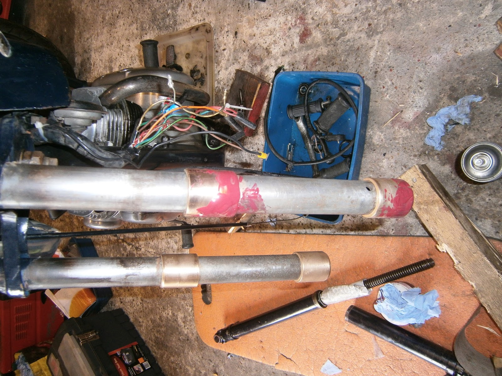
I decided to strip the front end of my Jubilee to investigate these faults, although the reason for the stuck forks was obvious on closer inspection; the LH oil seal was cracked and misaligned. (Note in this blog Right and Left refer to position from the riders perspective; many of the pics I'm using are taken from the front of the bike in which case the orientation may appear to be reversed). Before starting work to remove the front wheel, mudguard and fork sliders the bike was mounted on its centre stand on 2 inch wooden block supports to raise the front wheel.
 |
| Front forks- note misaligned oil seal on left hand fork (RH from the front) |
 |
| Incorrectly aligned oil seal-close up |
The mountings for wheel and mudguard on this bike are shown in these pics: mainly because the parts diagrams are quite poor and I need a record of how it should go back!
 |
| RHS front wheel steady bar from mudguard passes through the fork and terminates in cap-nut, Brake cable passes through an on-fork adjuster on the RHS, out of shot in this pic. The adjuster is mounted on the slider below the mudguard mounting. Note fork drain screw above wheel spindle- no oil in these forks! |
 |
| LHS same arrangement, damper retaining bolt visible on inside of fork. Head of sleeve nut tight against the outside of the fork, the spacer is visible on the inner side of the fork and this penetrates the dished cover (partly painted in blue) which itself is clipped onto the hub and rotates with it. |
Front brake cable slackened off at the leg adjuster and removed.
Mudguard steady stay top or cap nuts could be easily removed.
 |
| Remove mudguard stay end cap bolt |
 |
| Wheel spindle has a single nut on the LHS of bike- here this has been partially undone undone... the spindle can then be tapped through the wheel towards the right and pulled out releasing the wheel. Note collar fitted on spindle between fork and wheel to pass through oil seal is still present. As the sleeve nut is longer than the fork is thick, this implies that it must slip inside the spacer to avoid pushing the fork outwards. Note that the spacer has its chamfered side facing towards the fork. |
 |
| Spindle removed |
The wheel could then be removed easily as the bike was mounted on blocks giving enough clearance to allow it to drop out of the forks.
The front brake was very poor, the brake plate was removed to show that in fact linings looked in good condition. However the oil seal in the hub looks to have been leaking, bearings were rough and I think changing these and fitting new seals will be a good idea. Checking the parts list shows that the seal here is primitive- a felt disc sandwiched below a pressure cup. I'm not surprised it might leak and I think the way to go here is to upgrade to sealed bearings which do not require free grease. Bearings for the Jubilee front hub are 6202-2RS (35, 15, 11 mm) and I ordered two SKF from bearing boys. I also need to clean the braking area of the hub and of course to check that its is still round as this might explain the jerky feel of the brake.
 |
| Brake drum oil seal not looking good- grease inside looks dirty. Some corrosion on drum braking surface |
 |
| Brake back plate. Shoes look OK but indications of grease leakage. The plate-to-spindle fitting seems odd as its a two part removable system that in this case seems loose. |
The strip was continued by removing the mudguard: this is mounted to the fork via one bolt on each leg which passes through a bracket on the fork.
 |
| Easily removed, note brake adjuster bracket below mudguard mount. |
The steady stay is also bolted to the read of the mudguard by two bolts, these were also removed to free the steady stay.
The mudguard could then be fed out from between the fork legs. It needs to be twisted and passed out sideways towards the rear.
 |
| removing the mudguard note the steady stay released already |
The fork sliders themselves could then be removed. Neither of these contained significant oil!
Remove the fork top screws from the upper yoke.
 |
| Fork top screws removed from yoke, these also screw into the top of the springs so they must be removed before the slider can come off. |
The sliders could be removed easily by fitting a well-fitting bar through the spindle holes, place a foot on one end and strike the other with a hammer. Only a few blows are needed to pull each slider off its stanchion which remains welded in the yoke.
 |
| Slider mostly removed, note that the oil seal remains attached to the slider. The upper bush is seen poking out from under the shroud and the oil seal has stalled on the bottom bush. Note blocks under centre stand to raise bike front end. |
 |
| Slider removed from stanchion. Spring pulls out with the slider because it is screwed into the damper which in turn is bolted into the bottom of the slider. |
 |
| Bolt retaining damper (and thus spring) on inside of slider. Remove this screw and... |
 |
| Pull the spring and damper from inside the slider. |
 |
| Oil seal remaining on the slider... It looks almost like this is threaded onto the slider but in fact these are simply parallel grooves to grip the seal, not a true thread. |
 |
| ... The seal can be removed by sliding a hammer head down the slider to tap the rim of the seal, rotating the slider between blows |
In order to expose the bushes properly it was then necessary to remove the upper fork shrouds which also contain the headlamp mounting.
 |
| The upper fork shroud is retained by two bolts and a screw, this shows the top screw and the front bolt which also retains the headlight. |
 |
| and the second bolt is located in the lower yoke, this was also removed. |
All three fastenings were unscrewed, and the right hand shroud came away easily
 |
| Shroud removed, note upper oilite bush on stanchion |
Headlight Nacelle
The headlight was removed by unwinding the tape that held it on and popping the light unit out of the headlight shell. This should be retained by up to 5 spring clips between the light unit and the rim, and at least one screw bracket between nacelle and rim, but all were missing! Hence the need for the tape! The nacelle here is still attached to the left hand leg upper shroud which has yet to be removed. The hole in the headlight shell is actually square, yet the bolts holding it have no square facet. I think this must mean that the mounting system has been improvised at some point in the past and should have had some sort of square fixing- sadly I can't see this because of the poor resolution in the Norton parts list.

The mystery of the non-operational lights was largely solved since the contacts were not actually attached to the lights! The ears that should allow the contact holder to attach to the rear of the light unit were bent flat and so couldn't engage with the light unit body- easy fix at least..
 |
| The lower headlamp mount ...not there! |
The reason for the tape also became apparent as the headlamp mounting screw and adjusting system was missing entirely! I am not even sure what should be here since there is no illustration in the parts diagram. I have found a simple bracket affair in the owners club catalogue although I cant yet find a beam adjuster, but thinking about it the whole nacelle can be pivoted around its mounting bolts so I suspect one was never needed. The shell was also bent out of round so I will probably remove it entirely and attempt to improve its fit. The large grommet which should line the cable entry hole in the base of the nacelle is also missing.
Examination of bushes and stanchions.
Upper and lower bushes are soldered/brazed onto the stanchions, the upper bush is oilite and the lower one steel. All had some grooves marking them. Refitting the slider shows that there is certainly detectable play between slider and bushes, its not clear how much is too much but I think they will need to be changed. However replacements are unobtainable. I measured the bushes as fitted and also the ID of the slider- all very hard to do as there isn't really just one measurement!
Stanchion OD 32mm (1.25 inch); Slider ID 38 mm (1.5 "). Both bushes are 37.8- 37.9 mm in OD. I would expect clearances less than 0.1 mm and probably less than 0.05, so its likely that these have worn down a bit... Having no oil can do that!
I ordered 4 oilite bushes from Bearingboys (see below). Since most bikes have bronze bushes at top and bottom of the slider, I am hoping that the oilite type will be suitable for all as I cant find a source of steel bushes and I'm not sure what type of steel was used here. The alternative is to try and machine some from brass but the oilite should be easier so I'll try that first. Although these bushes have been ordered at the correct nominal size, I think that even so some machining will be necessary. Its also possible that the inside of the slider will be worn slightly so I will have to try and feel my way when machining. I don't know what sort of clearance is needed between the bushes and the stanchion, they are soldered on so presumably they were always a close fit but had to have to have room for the solder to flow down.
Bush Removal
Before removing I measured the bush and stanchion OD . These gave bush sizes of 38 mm OD and stanchion (ie bush ID) 32mm (1.5 and 1.25 inches respectively)The bushes are soldered or brazed on, mine appeared to be soldered as the excess visible around the top was silver rather than bronze. I melted this using a plumber's gas-can blowtorch. It needed app 2-3 min of heat and then the bushes could be tapped down with a hammer and punch... they are very hot!
 |
| Blowtorch to melt solder on bottom bush- here halfway removed... |
 |
| By sliding a hammer down the leg or using a punch on to bush top |
 |
| Lower bush off! Note that it fits into a recess on the end of the leg- measured at 30 mm diameter (1.2 inches). |
The top bush was removed in the same way, it spits a bit owing to the oil in the matrix of the metal.
 |
| Old Bushes, wear was clearly visible on lower (steel) bush but was also evident on the upper. Not surprising really since this leg had no oil in it at all. |
So far I have not managed to source any ready-made replacements, but I did find a source of oilite bearing bushes and bought four of 30mm (ID), 38mm (OD) and 40mm (long) bushes from Bearingboys.com (part no
OB303840 ). To my surprise the external diameter turned out to be an excellent firm sliding fit in the sliders and so I hoped this wouldn't need any modification. However, they require boring internally to fit over the stanchions, but as they are so small internally, they can be made to serve as either lower or upper bushes by boring them out to different IDs. The concern here is that oilite is not specified for the lower bushes and might not be strong enough- I have read of others using oilite here though when modifying Francis Barnett forks- which are the same design so maybe...?
An alternative is also to look at spares from suppliers dedicated to other bikes which used the same lightweight forks. There do seem to be plastic bushes available for the top bushes from AMC suppliers (these would need a flange removed) but the lower bushes presented a problem, steel lower bushes were listed (
nsamotorcycles.co.uk) but out of stock - and sadly likely to be so for the foreseeable future! Steel bottom bushes are listed as AMC lower bushes from
BRITISH Only Austria Fahrzeughandel GmbH in Austria part no
dba.02-1495*2.021495. I ordered two of these to see if they would fit. Externally they are too large to fit inside the Jubilee sliders but could be turned down to size. However the main problem with these is that I found they are sized to fit the full diameter (1.25 inch) stanchion which means that they are too large internally for use as jubilee bottom bushes owing to the cut-out at the bottom of the Jubilee stanchion. However I think they could be used in two ways: Firstly, I suspect that they would be suitable as top bushes because they seem to be made of some type of leaded steel and so do have some self-lubrication (remember oilite is specified in this position because there is little oil in this part of the fork); Secondly they could be fitted
immediately above the cut-out intended for the bottom bushes where the stanchion is the full 1.25 inch diameter. I'm not sure if it would be a good idea to refit the old bushes beneath these new ones to maintain geometry. However, if fitting the AMC bushes here it will be necessary to drill a hole in them as they will otherwise block the oil overflow hole which presumably lubricates the lower bush. They might even need another hole in the stanchion above them to supply them with oil too.
Machining all these bushes did present a problem, the oilites require boring internally to increase their ID, whilst the AMC bushes need to be reduced in OD. Apologies for the detail here but I am feeling my way with the lathe as well! I'm sure none of this would baffle a more experienced user. The usual way to turn these bushes would be to use a support such as a solid or expanding mandrel that slips as a tight fit through the bore in order to turn the outer dimension and some form of socket to support them whilst machining the inner dimension.
Dealing with the AMC bushes I had to exclude an expanding mandrel as they are just too expensive, but I turned an aluminium bar down to the required size. Eventually I made a stepped format, 1.2 inch followed by 1.25 inches, each matching the actual fork stanchion dimensions so that both bottom and top bushes would slip on as a firm fit when their internal diameters are right. This mandrel was also very useful as a plug guide whilst boring out the lower bushes internally. The mandrel could be loaded in the lathe chuck and supported with a centre so that the bush OD can be easily machined.
 |
| AMC bush being machined on solid aluminium mandrel- this was done before the mandrel was finished by turning it down again to create... |
 |
| ...separate sections for upper and lower bushes |
 |
| Testing the bush- a nice smooth fit inside the slider. |
The oilite bushes need to be bored out using a boring bar. Several sources comment on the inadvisability of using a reamer with oilite although I don't think it would matter in this case. The usual objection is that reaming causes the oilite to close up and loose lubricating ability. However, in this application the inner bush surface doesn't move at all (in fact its fixed) and all lubrication is needed on the external surface of the bush anyway. However I found it impossible to hold the bush firmly enough to ream it without damaging its external surface. I gave up on the idea of hollowing out a socket for them from a solid lump of steel as this simply needed too much material to be removed for my puny lathe to cope with, plus size limits on the jaws mean that really big sections don't fit easily. Finally even if I did this I would still need to find some way to support the end as only a short length would be held in the jaws compared with the socket projecting from them. Here I was rescued by the fact that the bushes I bought are longer than those which they replace so its possible to fit them in the lathe directly- taking care not to crush them, and then to bore them out internally using a boring bar. I could use the mandrel as a plug gauge to test as I approached each size. Any jaw marks are then limited to the excess length. However bear in mind that although I expected the oilite to be soft, it wears the tools very quickly. If using a carbide tipped indexing tool make sure you have spare tips before you start and change the cutting edge as soon as you notice that a) the cutting gets noisy and b) a second cut at the same setting starts to take off a substantial amount of material missed in the first pass.
 |
| Oilite bush held in lathe, boring in progress. |
Rather than cut off the excess length from the lower bushes I chose to counter bore to 1.25" ID for a depth of 0.75 cm. This allows the bush to ride up over the step in stanchion width providing a greater area between slider and bush and hopefully spreading the wear. I was careful not to leave the bushes too tight as oilite is a composite that's moulded rather than cast. I was worried that it could crack if its tight and gets stretched too far as its fitted so I wasn't going to leave them so tight that they needed a lot of force to push them into place on the stanchion. This runs the risk that they may be too loose but I used the AMC bushes to gauge the level of tightness required and hopefully the solder/loctite will take up any excess clearance.
 |
One bush in the hand- apparently worth two birds? Lower bush machined internally
to 1.2" diameter and recessed to 1.25" ID, 0.75 in depth. |
I made a 30 degree chamfer on the lower edge of all bushes to help with the oil seal which oddly has to slip up over the bushes before sealing around the stanchion above them!
 |
| chamfer to lower edge of bush. |
The final step was to check fit again- here I found that after machining the bush was no longer quite such an obliging fit in the slider; perhaps it had distorted a little around the ends? In any event I had to fit the bush onto the mandrel and machine the surface lightly- really only taking off a little at each end of the bush before it would slide into the slider again.
Having made all 4 bushes I set about fitting them. The originals were apparently soldered into place. I did try this but I have to say I found it impossible. Firstly, if the bush is heated it oozes oil- oil that it presumably it needs for its function, but secondly that oil prevents the solder from running down between bush and stanchion. If there is a way to do this then it must be a special knack. Maybe you heat the stanchion and melt solder onto it but don't heat the bush directly. Perhaps its possible to then slide the bush up over the hot molten solder? Anyway having burned my fingers and ruined the lubricating properties of one bush (which I remade) I decided to use Loctite 603.
 |
| Loctite 603, oil tolerant engineering adhesive |
I like to think that this wasn't around when the soldering approach was adopted but I really don't know. Anyway this is incredibly sticky stuff. I coated the inside of each bush with the sticky green goo and then slipped it up the stanchion twisting to spread the glue. It stuck almost at once although I left it overnight to make sure. I want to test the strength before I reassemble.
 |
| New bushes on front stanchion, old bushes still on the other. Note that the new bushes are longer than the old and I hope will therefore wear a little better. |
The new bushes are longer than the old which I think will help with wear.
 |
| Lower bush, oil hole free |
 |
| Upper bush... yes the observant amongst you will notice that owing to a fit of madness I fitted this one upside down! The chamfer should be at the bottom.... Doooohhhhhh! I decided to leave it as removing it would probably damage it beyond use. |
Both bushes required dressing with 800 grit emery before the slider would slide smoothly over them. I think the oilite tends to bulge out as its tapped upwards. I found some of the bushes needed rather more than a light dressing (!) in which case I used a coarser grit but moved up through the grit numbers to 800 once the fit had been achieved so that the bushes still looked shiny and unscratched. I then cleaned the stanchions and bushes thoroughly and test-fitted the sliders to both sides. The new bushes had completely eliminated the play present on the other stanchion so I am satisfied that rebuilding should lead to satisfactory fork performance.
Tested after 24hrs- adhesion is beautiful!! Bushes are on solidly and will not move.
I carefully cleaned up the stanchions and bushes as well as inside the sliders as well as I could. The bottom of the stanchion is a bit like a cloven hoof; there are two depressions I suspect designed to allow debris and crud in the oil to fall clear of the working action of slider over bushes. However this is also tricky to clean and really needs a long bottle-brush. I used a pointed cane and some rag to do the best I could. I don't think it was perfect. I also cleaned out the binding grooves that grip the oil seals around the top of the sliders. These were full of grit and paint so I used a wire brush to clear them.
 |
| cleaned grooves at top of stanchion to grip the oil seal. |
I had been worried about how to fit the oil seals but in fact both pressed into position beautifully with just firm hand pressure. They seated nicely around the lowest of the retaining grooves. However the fact that the seals seem to need less pressure to fit than expected might explain why one was out of position in the first place. I hope that cleaning the grooves will allow them to grip the slider and hopefully they won't come adrift again. If I ever have to do this job again I think I will use some Loctite to get a more positive location.
 |
| needs two hands to press on- but I had to hold the camera! |
 |
| Oil seal seated in position. |
Please note... This is a REALLY good time to refit the fork shrouds!!! As I found later to my cost, they can't go on after the slider so need to go on NOW before you assemble and fit the slider spring combo. You dont need to remove them in order to disassemble the forks and I forgot that I had also stripped them. Consequently I had to undo everything and refit once the shrouds were on- much easier the second time around though!
Next I inserted the damper/spring combo into the slider and fixed it in place with the retaining bolt at the base. I was wary of damaging the oil seal on the spring as there is likely to be a good deal of flapping about as I tried to fit the slider so I used an old padded envelope around the spring to protect the seal until I was in position to fit.
 |
| I tried to keep the stanchion upside down whilst I was moving it so that the spring didn't rub on the seal. Note padded envelope wrapped around spring to protect seal edge. |
I cut a cone from an old washing-up liquid bottle as shown, shorter side equalled the diameter of the spring andthe longer was greater than the diameter of the bushes. Make sure that there are no labels stuck to it as it needs to be smooth.
 |
| seal fitting tool! |
I applied assembly (oil-soluble) grease (red) to the bushes ...
 |
| Ooops... where are those shrouds??? |
... and also to the plastic cone, as well as squirting a little engine oil into the sliders before inserting the springs inside the stanchions and pushing the sliders up.
 |
| Note- If like me you stored the yoke screw in the top of the spring- take it out before fitting the slider! |
 |
| "Seal tool" in use. the seal is well greased and the plastic also. Its curled around the spring forming a cone that expands from spring to the lower bush diameters. As you push the slider up the seal rides easily up and over the bush. If the plastic isn't quite big enough (as in my case) I had to twist the slider and or the plastic cone to ease the seal lip up and over the bush all the way round. |
If you fold the plastic greased cone around the spring it forms a sloping cone up which the oil seal rides quite naturally, slipping its lip over the bush. I hadn't quite got my dimensions right and had to twist the plastic cone a bit to get the seal lips fully over but it was nonetheless very effective. If I was doing this job again I'd measure the cone more carefully- but I'm only doing this once and ... hey,
 |
| Slider and seal in position. |
I only had one bottle of wash-up liquid! The seal moved up onto the bush and I could them pull the cone out and slide the slider up to the next bush where the process was repeated. I found that the lack of chamfer on one of my bushes was no problem and this method worked well on that one as well.
Incidentally- since the seals do fit onto the sliders using hand pressure alone, it should be possible to fit the seals to the stanchions on their own, easing them over both bushes before the sliders are slipped up and the oil seals pressed in. This might be an easier method but I didn't try it.
The screw was then fixed at the top of the spring/yoke and the sliding action checked. This was fine so I made sure that the drain plug was back in position at the base of the slider before removing the yoke spring screw again. I then added 80 ml oil to each fork. I used 10/40 oil for this as I'm going to change it for fork oil in a little while. I wanted to make sure that the slider and spring et. was clean so I'll operate the forks for a short while before I drain this to flush out any muck and refill with fork oil (10/30 or straight SAE20).
Overall the reassembly was problem-free once the bushes were dressed. I was then able to refit the mudguard and front wheel ... and its "Job Done!" - Only the MOT will show whether its been done well enough but I think there is a vast improvement in play in this area.


Thanks Mike, your guide was very useful in helping me dismantle my James Captain forks!
ReplyDeleteP.s. Where did you get the replacement seals from?
ReplyDeleteGlad this helped! The seals came from the Norton Owners club shop. I must get back to this bike and sort out the motor- needs a rebore, and the clutch (new bush). However its all waiting on finishing the car!
ReplyDeleteFantastic guide Mike! Absolutely brilliant, really helped me out after the powder coater didn’t cover my bushes when they shot blasted the forks! You can now get oilite bearings almost exactly the same size from simplybearings.co.uk I just needed to dress the insides a touch with a flapper wheel then glued them on with loctite 938.
DeleteGreat site, thanks! I really like it.
ReplyDeleteHi Mike
ReplyDeleteI know this is an old post but hope this finds its way to you.
Your fork rebuild guide is very good and doing the rounds on Facebook at the moment. I run several Francis a Barnetts and have rebuild a few sets of forks. I even measured the bushes but lost the mail with it on.
Can you please tell me is these are correct before I try to purchase some bushes.
Top Bush 38mm OD and 32mm ID
Bottom Bush 38mm OD and 30mm ID
The old bushes I have are 32mm in length
I notice the Norton has a steel bottom bush but the FB had both Oilite Bronze bushes.
Hope this gets to you.
Regards
Ken Booth
kenny34123@yahoo.co.uk
Hi Ken, just done my jubilee forks and yes that was the dimensions of my replacements. Got them from simplybearings.co.uk
DeleteHow does the chrome shroud ends come off, mine are rusted and req renewing or Re chroming ?.
ReplyDeleteJust heat them up and they’ll come off with a big pair of pump pliers.
ReplyDeleteGreat site. Easy to follow instrucions. Most helpful. Many thanks
ReplyDeleteProvan